EmbLogic's Blog

Runqueues

The add_to_runqueue( ) function inserts a process descriptor at the beginning of the list,
while del_from_runqueue( ) removes a process descriptor from the list. For scheduling
purposes, two functions, move_first_runqueue( ) and move_last_runqueue( ), are
provided to move a process descriptor to the beginning or the end of the runqueue,
respectively.

Posted in Uncategorized | Leave a comment

The list of TASK_RUNNING processes

When looking for a new process to run on the CPU, the kernel has to consider only the
runnable processes (that is, the processes in the TASK_RUNNING state). Since it would be rather inefficient to scan the whole process list, a doubly linked circular list of TASK_RUNNING processes called runqueue has been introduced. The process descriptors include the next_run and prev_run fields to implement the runqueue list. As in the previous case, the init_task process descriptor plays the role of list header. The nr_running variable stores the total number of runnable processes.

Posted in Uncategorized | Leave a comment

socket function description

int socket(int domain, int type, int protocol);

The socket created is one end point of a communication channel. The domain parameter specifies the address family, the type parameter specifies the type of communication to be used with this socket, and protocol specifies the protocol to be employed.


int bind(int socket, const struct sockaddr *address, size_t address_len);

The bind system call assigns the address specified in the parameter, address, to the unnamed
socket associated with the file descriptor socket. The length of the address structure is passed as address_len.


int listen(int socket, int backlog);

A Linux system may limit the maximum number of pending connections that may be held in a queue.Subject to this maximum, listen sets the queue length to backlog. Incoming connections up to this queue length are held pending on the socket; further connections will be refused and the client’s connection will fail.

int accept(int socket, struct sockaddr *address, size_t *address_len);

The accept system call returns when a client program attempts to connect to the socket specified by the parameter socket. The client is the first pending connection from that socket’s queue. The accept function creates a new socket to communicate with the client and returns its descriptor.

int connect(int socket, const struct sockaddr *address, size_t address_len);

The socket specified by the parameter socket is connected to the server socket specified by the parameter address, which is of length address_len. The socket must be a valid file descriptor obtained by a call to socket

Posted in Uncategorized | Leave a comment

socket

In sockets

five main functions that r used are:

socket() , bind(), listen(), accept() and close()

Posted in Uncategorized | 1 Comment

The Current Macro

The pairing between the process descriptor and the Kernel Mode stack offers a key benefit in terms of efficiency: the kernel can easily obtain the process descriptor pointer of the process currently running on the CPU from the value of the esp register. In fact, since the memory area is 8 KB (213 bytes) long, all the kernel has to do is mask out the 13 least significant bits of esp to obtain the base address of the process descriptor. This is done by the current macro.

Posted in Uncategorized | Leave a comment

esp register

The esp register is the CPU stack pointer, which is used to address the stack’s top location.
On Intel systems, the stack starts at the end and grows toward the beginning of the memory
area. Right after switching from User Mode to Kernel Mode, the kernel stack of a process is
always empty, and therefore the esp register points to the byte immediately following
the memory area.

Posted in Uncategorized | Leave a comment

parallel port

After a driver has requested the range of I/O ports it needs to use in its activities, it must read and/or write to those ports. To this end, most hardware differentiates between 8-bit, 16-bit, and 32- bit ports.

Posted in Uncategorized | Leave a comment

The Task array.

Processes are dynamic entities whose lifetimes in the system range from a few milliseconds to months. Thus, the kernel must be able to handle many processes at the same time.The
kernel reserves a global static array of size NR_TASKS called task in its own address space.
The elements in the array are process descriptor pointers; a null pointer indicates that
a process descriptor hasn’t been associated with the array entry.

Posted in Uncategorized | Leave a comment

Parallel port

To use parallel port we need to allocate region using following  function

struct resource *request_region(unsigned long first, unsigned long n, const char *name);

We can also check whether region available or not by this function

int check_region(unsigned long first, unsigned long n);

Posted in Uncategorized | Leave a comment

parallel port usage

To test parallel port we can do the following step:

  • Create a node by  mknod /dev/parlelport c 61 0
  • The module can now be installed, parlelport. You can check that it is effectively reserving the input/output port addresses 0x378 with the command:

cat /proc/ioports

  • To turn on the LEDs and check that the system is working, execute the command

echo -n A >/dev/parlelport

This should turn on LED zero and six, leaving all of the others off.

  • You can check the state of the parallel port issuing the command:

cat /dev/parlelport

Posted in Uncategorized | Leave a comment

POSIX threads

Lightweight processes should not be confused with user-mode threads, which are different
execution flows handled by a user-level library. For instance, older Linux systems
implemented POSIX threads entirely in user space by means of the pthread library; therefore,a multithreaded program was executed as a single Linux process. Currently, the pthread library, which has been merged into the standard C library, takes advantage of lightweight processes.

Posted in Uncategorized | Leave a comment

I2c protocol

One of the most common communication buses in the world, and hence one that should be well understood by prospective engineers, is the I2C bus.  It may not be as well known as USB or Ethernet, but much of the world of electronic devices is completely dependent on it.

I²C (Inter-Integrated Circuit) is a multi-master serial single-ended computer bus invented by Philips that is used to attach low-speed peripherals to a motherboard, embedded system etc.

The I2C bus physically consists of 2 active wires and a ground connection. The active wires, called SDA and SCL, are both bi-directional.

SDA — Serial DAta line

SCL –  Serial CLock line.

Every device hooked up to the bus has its own unique address, no matter whether it is an MCU, LCD driver, memory. Each of these chips can act as a receiver and/or transmitter, depending on the functionality.

MASTER & SLAVE

The I2C bus is a multi-master bus. This means that more than one IC capable of initiating a data transfer can be connected to it. The I2C protocol specification states that the IC that initiates a data transfer on the bus is considered the Bus Master. Consequently, at that time, all the other ICs are regarded to be Bus Slaves.

.

I2C Bus

Lets consider the following setup and assume the MCU wants to send data to one of its slaves

First, the MCU will issue a   START condition. This acts as an ‘Attention’ signal to all of the connected devices. All ICs on the bus will listen to the bus for incoming data.

Then the MCU sends the ADDRESS of the device it wants to access, along with an indication whether the access is a Read or Write operation (Write in our example). Having received the address, all IC’s will compare it with their own address. If it doesn’t match, they simply wait until the bus is released by the stop condition. If the address matches, however, the chip will produce a response called the ACKNOWLEDGEMENT signal.

Once the MCU receives the acknowledge, it can start transmitting or receiving DATA. In our case, the MCU will transmit data. When all is done, the MCU will issue the STOP condition. This is a signal that the bus has been released and that the connected ICs may expect another transmission to start any moment.

TRANSMITTING A BYTE TO A SLAVE DEVICE

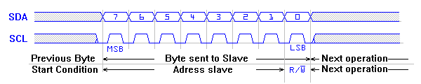
Once the start condition has been sent, a byte can be transmitted by the MASTER to the SLAVE.
This first byte after a start condition will identify the slave on the bus (address) and will select the mode of operation. The meaning of all following bytes depends on the slave.

Waveform sending byte

An IDLE bus condition is defined as having both SDA and SCL high. A ‘START” condition is generated by the Master, followed by 7 bits of address, then a ReadWrite bit.  If a slave device detects an address match, it will send an ACK by driving SDA low during the next clock cycle; if no slave recognizes the address then the SDA line will be left alone to be pulled up high.  Following a successful ACK, data will be either sent to the slave device or read from the slave device (depending on what was indicated by the Read/Write bit).  Therefore, each byte is 9 bits: either 7 address plus one R/W plus one ACK/NAK, or 8 data plus one ACK/NAK.  The last data byte of a transaction should generally be followed by a NAK, to indicate that it is intended to be the final byte.  After this, either a STOP or a ReSTART should be issued by the Master.

Sample bitstream of the I2C protocol. \includegraphics[clip=true]{i2c-02}

Posted in Uncategorized | Leave a comment

Device Drivers in OS Environment

DEVICE DRIVER ::A device driver is a software, it’s not a hardware. A driver is a code which is completely specific to a hardware device and brings all the functionality to it. Without a driver in OS environment an application can’t make use of the hardware functionalities. Driver has to be in the kernel space in the case of monolithic kernel. It has to be in the privileged environment, it is so because in the privileged space/kernel space only the driver code has the ability to perform operations on the hardware. This kind of code can also be written for micro controllers where there is no OS.
Applications reside in a non privileged environment and have to rely on services provided by drivers to access the hw. This is done to reduce complexity and making the use of information hiding that is encapsulating and providing abstraction, so as to make the applications easier and safer to write in less time. In linux the drivers are the kernel services to access the hw functionalities.

OS KERNEL :: The operating system is not what you see on your display device or your monitor. The operating system consists of a kernel(the soul of your system), shell and utility programs or api to
access services and interacting with the hardware. The most important part rather the soul of an operating system is it’s kernel. The kernel’s job is to manage memory, do task scheduling, bring functionality to the device through device drivers and provide services for interprocess communication.
The kernel may be MONOLITHIC or a MICRO KERNEL. A monolithic kernel is a kernel where every part of the it is just build into it as a unit and has a disadvantage that if any thing goes wrong with any part of the kernel code that may be for example a device driver code trying to dereference an invalid address the whole SYSTEM crashes. Micro kernels have an advantage over this, as the device drivers and rest of the kernel services lie out side the kernel space and kernel just supervises each of the operations as a server and whole of the kernel is based on CLIENT AND SERVER computing model. Thus the kernel has less probability to crash.

DEVICE DRIVERS :: We use peripheral devices. These are the mouse, keyboard, printer, Network devices to send and receive network information. These devices are not directly connected to the cpu through a bus, they are first connected to a controller or a bridge device (Device IO controller) through a bus that is referred to as peripheral bus. The device IO controller may be UART controller, USB controller, VGA controller, NETWORK controller etc. This controller is again further connected to the processor through the controller bus (in case of a PC set up).
Example :: USB is a peripheral bus and PCI is a controller bus.

DEVICE DRIVER LOGIC :: We cannot directly perform operations on the device as we have the device controller in between. We need to give commands to the controller. Then on behalf of the our code the controller will do the job. Thus our first issue is to send commands to the controller according to the functionalities offered by the device. We must know what all operations this device can support or simply options on the device.
Thus our driver code is broken up into two parts ::

#1 Low Level Driver (LLD):: Interfacing with the controller.(This code remains the same for a specific controller)

#2 High Level Driver (HLD) :: Code specific to the peripheral device functionality.(Without the knowledge of which device you are talking we can’t write this code.)

Interfacing with the controller is called the low level drive. The low level drivers provide the code to interact with the controllers. The high level drivers are only about what to execute on the device.

We need this kind of division because there are different controllers on different architectures. The usb controller for example may be different on different on different boards. If we mix both HLD and LLD in one code our driver will never be portable, will not be able to reuse our code. But if we divide this logically the HLD can remain same while the LLD can differ. The HLD must remain absolutely controller independent and reusable.

To make HLD independent of hw we hide the details of LLD and call it BUS MANAGER. The bus manager is similar to the virtual file system which is an abstraction hiding all the complexities of othe file systems.

Writing low level driver is writing board bring up driver. We have two domains of device driver community BSP driver community and and PERIPHERAL driver community. Simply BSP driver community write LLD and PERIPHERAL driver community write HLD.

In PC domain we don’t really have to worry about the LLD because it comes along with the kernel sources. But in the embedded domain we may have write a little bit of LLD.

HIGH LEVEL DRIVERS :: The high level drivers or the peripheral device drivers reside in the kernel space. The applications are in the user space which use these drivers. Now we have to provide an interface through which the applications can request like do this operation do that operation. Also we communicate with the hard ware which done through the API of low level driver. Now writing this driver is also broken down into two parts.

#1 Interfacing with the application.(This code is specific to design of kernel)(SYS CALLS in Linux)
#2 Interaction with hardware.(This code is specific to bus manager)

Exploring the interaction with hardware requires the reading and understanding of kernel sources.

Linux provides three different approaches for writing interfacing with the application.
Linux Driver Classes =
#1 CHARACTER DRIVER MODEL
#2 BLOCK DRIVER MODEL
#3 NETWORK DRIVER MODEL

The approach we choose depends upon two factors.
#1 Synchronous communication.
#2 Asynchronous communication.

Asynchronous means :: An application will not directly interact with the driver instead it will submit a request and go back. The driver will then carry out the operations. Application will either poll for the operation to be done or the driver will send a signal to the application that the job is done.

Synchronous means :: An application will make a call to a function and wait for it to return.

Example :: A char driver can be for pci bus, it can be on usb bus and so on.

Ankit

15/02/11

Posted in Uncategorized | Leave a comment

please upload the documents regarding signals….

Posted in Uncategorized | 1 Comment

Programmable Interval Timer

Linux programs the first PC’s PIT to issue timer interrupts on the IRQ0 at a (roughly) 100-Hz frequency, that is, once every 10 milliseconds. This time interval is called a tick, and its length in microseconds is stored in the tick variable. The ticks beat time for all activities in the system; in some sense, they are like the ticks sounded by a metronome while a musician is rehearsing.

Posted in Uncategorized | Leave a comment